

Transfluid 27CKR U.S. style R.S.B. Fluid Coupling
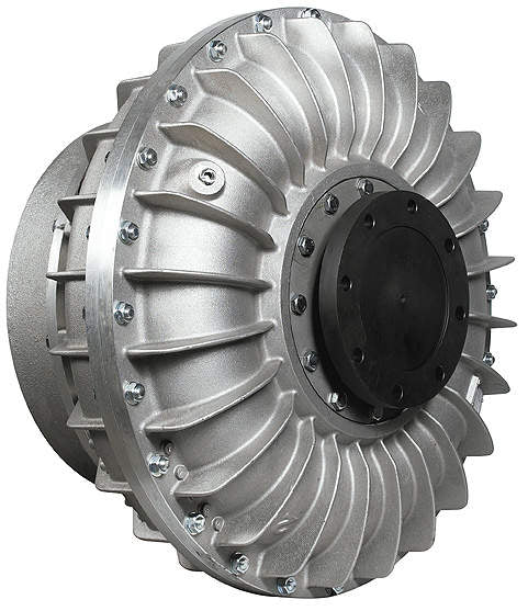
27CKR U.S. style R.S.B. Fluid Coupling – Maximum 1000 Horse Power at 1800RPM
complete with Flexible Output Coupling
The TRANSFLUID coupling (K series) is a constant filling type comprising of three main elements:
1) Driving impeller (pump) mounted on the input shaft.
2) Driven impeller (turbine) mounted on the output shaft.
3) Cover, flanged to the output impeller, with an oil-tight seal.
The first two elements can work both as pump and/or turbine.
2. OPERATING CONDITIONS
The TRANSFLUID coupling is a hydrokinetic transmission.
The impellers perform like a centrifugal pump and a hydraulic turbine. With an input drive to the pump (e.g. electric motor or Diesel engine) kinetic energy is imparted to the oil in the coupling. The oil moves by centrifugal force across the blades of the turbine towards the outside of the coupling.
This absorbs the kynetic energy and develops a torque which is always equal to input torque thus causing rotation of the output shaft. The wear is practically zero since there are no mechanical connections. The efficiency is influenced only by the speed difference (slip) between pump and turbine.
The slip is essential to the functioning of the coupling: there could not be torque transmission without slip! The formula for slip, from which the power loss can be deduced is as follows:
slip %=((input speed – out speed) / input speed) x 100
In normal conditions (standard duty) the slip can vary from 1,5% (large power) to 6% (small power).
The TRANSFLUID couplings follow the laws of all centrifugal machines:
1) Transmitted torque is proportional to the square of input speed;
2) Transmitted power is proportional to the cube of input speed;
3) Transmitted power is proportional to the fifth power of circuit outside diameter.
Please contact info@kraftpower.com or call 800-394-0078 for more info.